Right now I am working on the body shell mostly. My plan is to first finish the body shell and then work on the arms and legs. Once those are complete, I'll go back to the body and finish up with the internal structure and linkages between the limbs and the body.
Besides that, not much has happened... I am kind of taking things slow right now...
Tuesday, August 27, 2013
Sunday, August 18, 2013
What To Do Next?
I was planning on working on the portion of the neck that is located inside the body such as the two steppers that will be moving the lower and upper neck pieces.. however, I need to know what the inner structural frame is going to look like so I can find where to attach these mounts and brackets to.
So, I can either start working on the body such as the inner frame or I can work on the arms, starting from the shoulder.. but that would also need some information on how to attach the arm to the body. Hmm.. so it looks like I should start the body now, which will take a long time just from seeing the current revision.
Alright then, I guess I'll grab a snack and then start working again...
Saturday, August 17, 2013
Minor Changes To The Neck
After seeing the (almost) final design for the neck, I decided to change the mechanism for the lower neck pivot. It was originally a timing belt (GT2 3mm) but due to the space constraints, I changed it to a ANSI 25 roller chain and sprocket.
This should allow me to put in a larger diameter sprocket at the neck pivot than what I had with the timing belt. This configuration coupled with one or two step down sprockets should give me enough torque to move the neck and head assemblies.
At the moment, I am pretty much finished with the neck sections outside of the body, so now I will work on the mechanisms to drive the lower and upper pivots of the necks. They will both be powered by stepper motors for now. The lower pivot will have a counterspring for assistance but I don't know if I have room to add a counterspring for the upper pivot.
One last thing: Once Revision A is complete, I'll go back and virtually assemble WALL-E piece by piece to make sure I have the tools and clearance to assemble the components properly. During this time I will also take a look at the BOM and see if we can make small modifications in order to use the same fasteners as much as possible to minimize costs. I'll make some final changes and then I will start creating a Revision B for production with assembly drawings and whatnot.
Alright, time for a little break and then I'll get started on the two stepper motors and their mounts/linkages.
Thursday, August 15, 2013
Neck Almost Complete
I am almost done with the neck assembly. I just need to finish up on the linkage connecting the upper pivot to the upper neck body assembly. Then I'll need to create the neck outer shell pieces such that I can fabricate them.


That's about it for today. Time to get some rest.
Wednesday, August 14, 2013
More Progress With The Neck
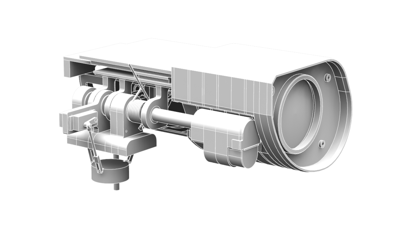
I spent a lot of time today finding the right timing pulleys that would fit inside the neck... hours upon hours. I finished up the upper swivel portion of the neck and then started working from the bottom up of the neck. So, here's what I have so far:


Tuesday, August 13, 2013
Neck Almost Complete
I am almost done with the neck now. I still have to finish up on the fastener that connects the swivel base to the neck and how the rear eye connector cables attach to the neck. I should have at least one of them done by tonight.
Unfortunately, Blogger is having issues with the image uploader so I'll update this post once it starts working again.
Edit: Here's the image

Unfortunately, Blogger is having issues with the image uploader so I'll update this post once it starts working again.
Edit: Here's the image

Monday, August 12, 2013
Finally Working On The Neck
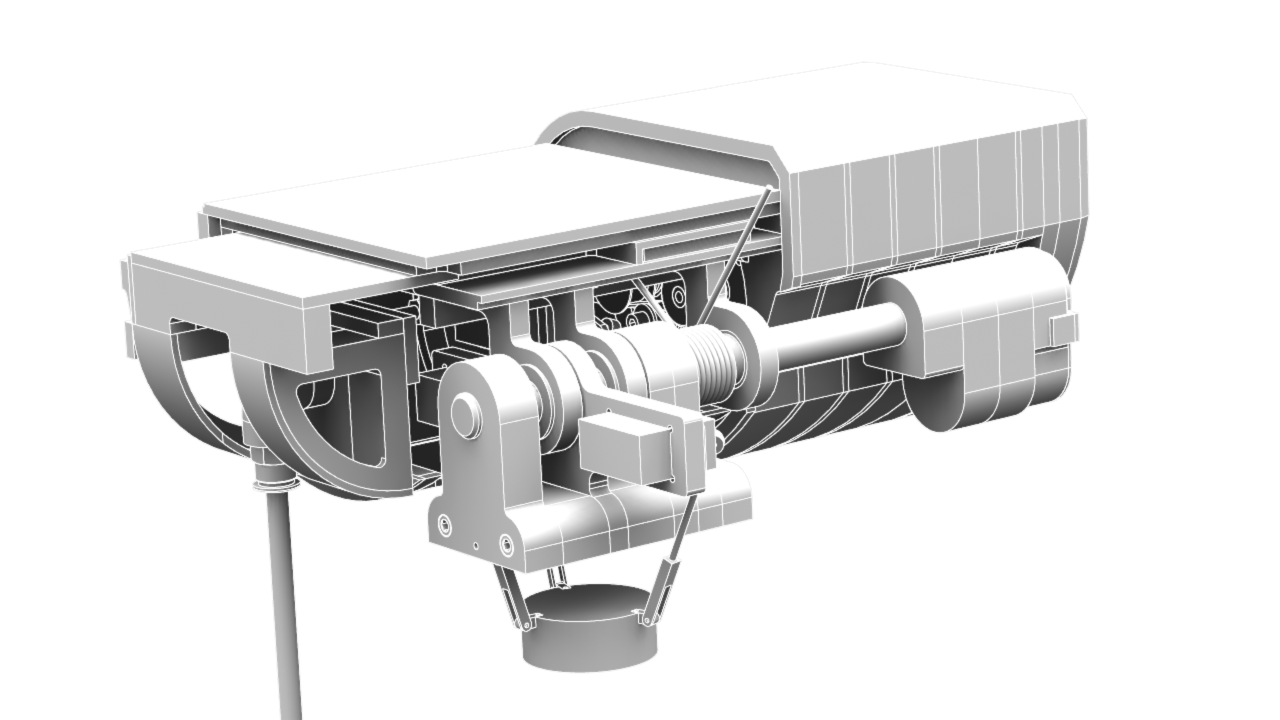
After a long time troubleshooting the head pivot, I started working on the neck. I wanted to directly attach the servo to the swivel base but the lack of up and downstops, as well as additional shaft supports, forced me to alter the design slightly. Due to the space restraints, I ended up with the following:


Attached to the swivel base is a d-shaped shaft that is internally threaded on one end. The shaft is attached to the swivel base by a fastener and some spring washers.. I'll probably have to add some Loctite on there as well. The shaft goes through an upper and lower ball bearing and between them is a GT2 timing pulley. The timing pulley will connect to the other timing pulley, which is connected to the servo via a 25T spline to 0.375 diameter shaft adapter. That shaft will be supported by an upper bearing as well.
I also made some grooves behind those pieces for wiring but the biggest problem I'll have is getting the correct contours when machining. I'll probably have to sand down some of the edges where the cutter can't reach.
Two things I still have to work on is the belt tensioner and a way to connect this piece to the lower neck. I will work on that tomorrow...
Sunday, August 11, 2013
Head Pivot Support
So here's the current head pivot support mechanism:


The top side consists of a spring loaded ball transfer rolling on the lower spring loaded plate. The one concern that I have is the range of motion for the two pieces. During compression they should be fine but during extension, they might run out of travel. So, I can either put a retaining lip to limit the max extension or design another mechanism entirely. What I'd like to do is find a shorter clevis for the three pivots. If I can find a metal clevis that is less than 24-30mm long, then the current design should work...
Edit: So I've replaced the 30mm long aluminum clevis with a 24mm long plastic clevis. The reduction of 6mm did make some difference and I am satisfied with that for now. I went ahead and started working on the neck swivel assembly but there's just not enough room to fit an actuator in there for the swivel movement! My previous design used what I thought was an acceptable servo but it turns out it was a retract servo, meaning it only stays at the min or max position... So, I've found some low profile servos I might be able to fit in there but there might not be enough room... Time to rethink!
Saturday, August 10, 2013
Crisis Averted...?
So, I think I managed to redesign the neck mechanism to something that will work..


It seems to work using the motion study in Solidworks but, it seems awfully flimsy.Since the specifications were not listed for the servo arm screw sizes, I guessed that it would probably be an M3 screw. With that information, the only ball rod ends I could find were M3's... The pins between the clevis and the arm is a M2... so, I'm a little worried about that. Those three linkages are holding up the entire head! I'm trying to find the smallest gas spring or RC spring shock to attached between the swivel base (the very bottom piece) and the pivot base in order to relieve some stress off of those linkages. Unfortunately, the shortest pieces I could find were 65mm long - I need something between 40-50mm... If it doesn't work out, I'll end up just making it a fixed joint with no pitch and roll.
In other news, I've added a torsion spring halfway down the pivot shaft to assist the servos that will be pivoting the eyes. The assortment of springs were limited for the 3/4 rod so hopefully this one will work.
Now, I'll be working on the eye pivot servo mount/linkage and the reinforcing the head tilt linkages on the bottom.
Edit: Here's an updated mechanism for the neck:
I flipped the servo and the two linkages to the front side of the swivel base. Hopefully, it'll allow the ball rod ends more clearance than before. What I'm also trying to figure out is at which location the servos will be stressed the least... it's already bad enough that the neck joint is so far back from the front of the head...
Friday, August 9, 2013
We've Got A Problem...
Soooooo, the neck mechanism in it's current version does not work. I have one or more joints that need to be changed to a revolute joint instead of a spherical joint. I've been working all day yesterday and today in order to find a working design.
For the past few hours I've designed a new mechanism using derailleur cables, cylinders, and pistons... it worked in theory but it would be too time consuming and costly to actually fabricate it.
Just after giving up on that, I found that a simple tweak in the current mechanism will work apparently. I have to look at it more in Solidworks to make sure it really works out...
I will give an update later tonight if I get a chance to finalize a new design for it.
Edit: It seems that it will work in theory. I just need to find the correct length of the rods and their locations relative to each other. This will take a lot longer than I thought... I'll leave it for tomorrow.
Wednesday, August 7, 2013
Almost Finished With The Head
Today, I completed the rear connector using off-the-shelf pipe connectors and tubing. I also redesigned the how everything bolts together in the rear of the head... and finally, I decided on which servos I will be using for both the eye pivot and the head pivot: TGY-5521MD. So far, it starting to look like WALL-E's head once again, but the cost is going up and up... I originally budgeted about $2,000 for this project so hopefully we can stay under budget!


Alright, time for some sleep!
Tuesday, August 6, 2013
Still Working On The Head
I've been working on the head all day today and I'm still not done. I finished some of the decorative cover pieces but I had to rework the side cover frame. At this point, I hope the two angle brackets can support the weight of the front half of the eye. If not, we're in big trouble...
Looking at what I have so far, maybe it's starting to become a little too complicated? I've done my best to design the pieces such that I can make them from a CNC machine but I don't know for sure if it will be possible..
Oh, well.. here's the latest render of the rear half of the eye:


Looking at what I have so far, maybe it's starting to become a little too complicated? I've done my best to design the pieces such that I can make them from a CNC machine but I don't know for sure if it will be possible..
Oh, well.. here's the latest render of the rear half of the eye:


Monday, August 5, 2013
Eye Rear Progress
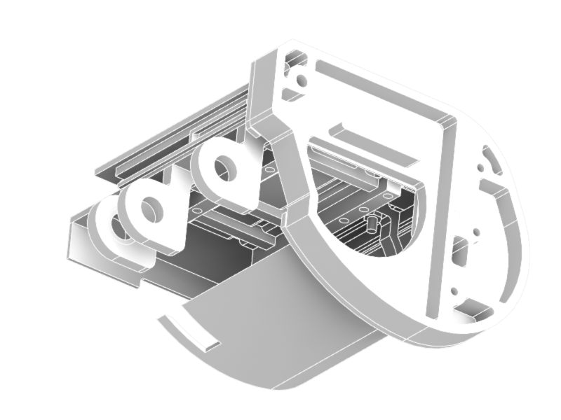
I've been working on the eye again today:


In this view, you can see the eye in/out mechanism located towards the rear of the eye socket. The hole at the bottom is for the eyebrow servomotor cables. The three pivot brackets as well as the rest of the decorative top covers are there too.
Now that I think about it, the servomotor opening might be too low.. hmm, I will have to double check when I get to the side covers sometime today or tomorrow. At this rate, I should be done with the eye by tomorrow or perhaps the day after.
Time for dinner. Bye.
Edit: Here's an updated view of the rear of the eye:

It's going to be very cramped back there. The one part that worries me the most is the angle bracket connecting the front and rear half of the eye. Hopefully, those three bolts will be able to hold.. if now, I will have to add a support bracket just inside the side cover piece, between the two mounting bolts.
As noted earlier, I had to adjust the opening for the servomotor cables because they were too low and showing beneath the bottom cover piece. Finally, I think I might have gone a little overboard with the two rows of bolts holding most of the rear pieces together. I might end up with two rows of three bolts...
It's getting late now, so that's it for today. Tomorrow, I will work on the rest of the rear pieces and if I'm lucky, I'll get started on his nose/eye pivot.
Sunday, August 4, 2013
Eye Front Complete
The front portion of the eye is now complete with machinable parts and off-the-shelf components I can purchase.


Besides some common fasteners, the only components that were not modeled in the front subassembly are the servo arm attached to the element base, the spring linkage connecting the servo arm to the eyebrow pivot, and a rubber layer between the eyebrow and the eyebrow resting location.
The eye socket subassembly was redesigned to be lighter weight and more compact than Rev. 0 but it is now comprised of more intricate pieces that I can hopefully fabricate on the CNC.


Time for little break and then I'll get back to work on the rear portion of the eye.
Edit: Here's an updated view of the eye with part of the rear-top cover and pivot brackets:

Saturday, August 3, 2013
Eye Socket Update
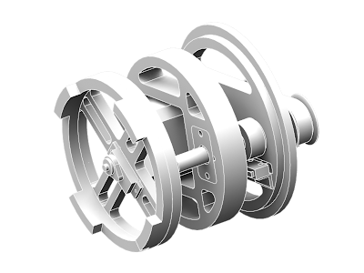
So here is the new internal structure of the eye socket:


As you can see, I've made some changes in reducing the weight. Also, it finally dawned on me that I didn't need the guide rod in addition to the lead screw. Since the lead screw is offset from the center, the outer PVC casing will prevent the rotation.
Tomorrow, I will make some changes to how the front element rings are fastened together and then I will finish up the rest of the eye socket (hopefully).
Good night.
Thursday, August 1, 2013
Rev. A
I have started working on Rev. A.
Rev. 0 was more to create a the outer shell in order for me to find ways to design the inner workings of WALL-E. Rev. A will be designed such that I can fabricate these parts on a 3-axis CNC router.
Here's the Rev. A version of the eye so far:


Rev. 0 was more to create a the outer shell in order for me to find ways to design the inner workings of WALL-E. Rev. A will be designed such that I can fabricate these parts on a 3-axis CNC router.
Here's the Rev. A version of the eye so far:

As you can see, it looks pretty similar to what I had before. Although the outer shell is similar, the inside structure has been changed greatly. In the original revision, I was planning on using thin sheets of balsa to create the curvature of WALL-E's eyes. Now, I will just stack slices of his eyes to create the same shape. Here's one of the slices:

Since this method will create a heavier assembly, I had to optimize the piece for weight and strength. Although the pieces seems intricate, the CNC router should be able to fabricate this part easily. The three holes you see are for the three guide rods that will hold all the pieces together.
Finally, here's an inside view of the head so far:

Tomorrow, I will start revising the eyebrow mechanism and perhaps start on the eye socket.
Subscribe to:
Posts (Atom)